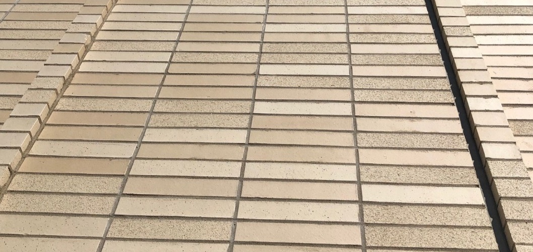
What is “Stack Pattern” masonry, and when does it need to be reinforced?
Masonry allows designers the creativity in determining how individual units will come together in a larger wall panel to form a desired aesthetic. Masonry veneers are also known for being a high-quality building envelope material and providing exceptional durability. One option which has become increasingly popular across Canada is to change a running bond pattern to a stack or other decorative pattern.
In masonry construction, a “running bond pattern” is the term given when masonry units overlap from course to course, typically expressed as the proportion of the unit length that overlaps (e.g. 50% running bond is when one-half of the unit overlaps the unit from an adjacent course), sufficient to provide bond in the horizontal direction of the wall. CSA S304-14 defines running bond patterns as those with head joints in successive courses that are horizontally offset at least 25% of the unit length. When there is no unit overlap from adjacent courses the term used is “stack pattern” and, in this case, head joints form a continuous vertical line in the wall. There may also be “decorative patterns” of masonry where there is some unit overlap, but it is insufficient to be considered a running bond pattern. The key consideration here is that stack and decorative patterns where less than 50 mm of the unit overlaps, are not considered to have sufficient bond in the horizontal direction alone and must be reinforced in the horizontal direction.
The purpose of this page is to highlight horizontal joint reinforcement requirements when selecting a stack or decorative pattern for a masonry veneer instead of a running bond pattern. Stack or decorative patterns used in masonry walls other than veneers may also require additional design considerations and could be subject to explicit restrictions on their use for some applications. Designers should consider the limitations for use of stack or decorative patterns in non-veneer walls contained throughout CSA S304-14.
Part of our Masonry Specification Series
Offering recommendations accompanied with background explanatory material to explain how these recommendations were formed. Click here to see the full series.
Disclaimer
The information contained here is intended to serve as educational content for designers, specifiers, or contractors. It is not to be relied upon for formal technical advice, as masonry projects may have details and considerations that are unique to a particular project and may be beyond the scope of the content of this page.
Recommendations
When specifying veneer walls built with stack pattern masonry, ensure that bed joint wire reinforcement spaced vertically at a distance no greater than 400 mm is used as per Clauses 8.1.2 and 8.1.3 in CSA A371-14.
Furthermore, it is the recommendation of CMDC that in all cases of veneer walls containing any horizontal bed joint wire reinforcement, the designer shall provide explicit details in the specifications and related contract documents such as drawings. Although prescriptive requirements are contained within CSA A371-14, it is strongly recommended that all reinforcement details be explicitly and clearly stated in the contract documents to avoid any possible miscommunication.
Discussion
There is a common terminology misconception with use of the term “stack bond” from the perspective of Canadian Codes and Standards. An explicit distinction was made in Canada to differentiate between running bond patterns and stack and decorative patterns. The use of the word “bond” is explicitly excluded from stack and decorative pattern terminology in the CSA Standards to avoid the implication that there is sufficient bond across continuous head joints alone. Without sufficient unit overlap between adjacent courses in running bond construction, it has been observed through decades of field experience that continuous mortar head joints, when left unreinforced, are insufficient to hold the vertical “stacks” of units together and to resist even nominal movement within the wall due to moisture, temperature, or loading related strains.
An example of a potentially problematic specification for veneers in stack pattern that does not take joint reinforcement into account can be seen below:
Example of potentially problematic specification:
3.03 INSTALLATION
.1 Coursing of Masonry Units
.1 Concrete Masonry Units:
.1 50% Running Bond
.2 Clay Brick Veneer Units:
.1 Stack Bond
.2 Install cavity walls, solid walls, and partitions in accordance with CAN/CSA A371-14
Unreinforced masonry veneers built with stack pattern can display significant vertical cracking at the vertical and continuous mortar joints shortly after installation. This weak bond along the height of stack pattern masonry needs to be supplemented in order to ensure the veneer does not suffer cracking beyond what would be typically expected in a masonry veneer with a running bond pattern.
8.1.3
For stack or decorative patterns where the bonding overlap is 50 mm or less, each wythe of masonry shall be continuously reinforced longitudinally in accordance with Clause 8.1, but the vertical spacing of the horizontal joint reinforcement shall not exceed 400 mm. This requirement shall apply to unit masonry walls and veneers.
CSA A371
Stack and decorative pattern masonry veneers always require joint reinforcement when constructed in accordance with CSA A371-14.
An important distinction is made in CSA A371-14 and CSA S304-14 when it comes to horizontal bed joint wire reinforcement required for masonry veneers. There are two distinct pathways for compliance depending on the pattern of masonry in the veneer:
Notes concerning bed joint wire for veneers
Veneers constructed in running bond with more than 50 mm of unit overlap from adjacent courses (ie. running bond)
- Horizontal bed joint reinforcement must be specified by the designer if it is required. It is not typical to require horizontal bed joint wire reinforcement in veneers with running bond patterns. Exceptional circumstances could lead to such a detail (e.g., local ordinances containing special seismic reinforcement provisions, concrete masonry veneers where extra considerations for shrinkage cracking is desired, etc.) but are not common across all locations and all building types.
- If explicitly specified by the designer, a maximum vertical spacing of 600 mm for horizontal bed joint wire reinforcement is given by CSA A371-14 Clause 8.1.2 e).
- A maximum spacing is not a conservative solution and the exact spacing, the gauge of steel, the wire pattern, and the corrosion resistance shall be provided by the designer in the contract documents.
Veneers constructed in stack or decorative patterns with 50 mm or less of unit overlap from adjacent courses (ie. stack pattern)
- Horizontal bed joint reinforcement is required when constructed according to CSA A371-14.
- Horizontal bed joint wire reinforcement shall be spaced at no more than 400 mm vertically per CSA A371-14 Clause 8.1.3.
- The size and type of horizontal reinforcement shall meet the size and configuration requirements specified in CSA A371-14 Clause 8.1.2 unless specified by the designer. To avoid confusion, the exact spacing, the gauge of steel, the wire pattern, and the corrosion resistance should be provided by the designer in the contract documents.
Stack and decorative patterns in masonry veneer require horizontal reinforcement when installed according to CSA A371-14. The minimum requirements are provided by CSA A371-14 Clauses 8.1.2 and 8.1.3. There may be other cases where either horizontal reinforcement is required in running bond patterns, or when horizontal reinforcement in stack or decorative patterns deviates from the minimums given in CSA A371-14 (e.g., stainless steel, larger gauge wire, or smaller vertical spacing). In both cases, it is the responsibility of the designer to provide those details in the contract documents.
It is recommended to masonry contractors to submit RFIs on all projects where required reinforcing is not explicitly stated. Reinforcing to the prescriptive requirements of CSA A371-14 can lead to a wide range of compliance options which may not sit well with some designers.
Return to Recommendations section. Return to the Specifications page.
Part of our Masonry Specification Series
Offering recommendations accompanied with background explanatory material to explain how these recommendations were formed. Click here to see the full series.

Have a question about anything here?
CMDC is made up of offices across Canada, connecting you with support through our team of technical staff.
Providing clarity and raising issues before they turn into real problems
As part of our overall effort to educate the design community and our contractor members, CMDC has compiled a collection of articles meant to address common areas of misunderstanding or confusion that have resulted in issues in past projects.


